'3D그래픽' 카테고리의 다른 글
| Ray Tracing Essentials - NVIDIA Developer (0) | 2020.04.25 |
|---|---|
| 튜링 어워드 수상자 (0) | 2020.04.02 |
| visualizing eigenvectors (0) | 2016.06.28 |
| Quaternion 사원수 (0) | 2014.07.15 |
| [미결] Vertex Array Object(VAO)와 Vertex Buffer Object(VBO)와의 관계? (0) | 2014.06.21 |
| Ray Tracing Essentials - NVIDIA Developer (0) | 2020.04.25 |
|---|---|
| 튜링 어워드 수상자 (0) | 2020.04.02 |
| visualizing eigenvectors (0) | 2016.06.28 |
| Quaternion 사원수 (0) | 2014.07.15 |
| [미결] Vertex Array Object(VAO)와 Vertex Buffer Object(VBO)와의 관계? (0) | 2014.06.21 |
| Is Simulating Soft and Bouncy Jelly Possible? (2) | 2020.04.26 |
|---|---|
| 튜링 어워드 수상자 (0) | 2020.04.02 |
| visualizing eigenvectors (0) | 2016.06.28 |
| Quaternion 사원수 (0) | 2014.07.15 |
| [미결] Vertex Array Object(VAO)와 Vertex Buffer Object(VBO)와의 관계? (0) | 2014.06.21 |
튜링 어워드 수상이 그래픽 쪽에서 이루어 졌다.
잊을까봐 기록 해 둔다.
Edwin Earl Catmull
https://dl.acm.org/profile/81100160637
Edwin Earl Catmull - Home
The ACM DL is a comprehensive repository of publications from the entire field of computing. It is ACM's intention to make the derivation of any publication statistics it generates clear to the user. Average citations per article = The total Citation Count
dl.acm.org
Pat M Hanrahan
https://dl.acm.org/profile/81100482576
Pat M Hanrahan - Home
The ACM DL is a comprehensive repository of publications from the entire field of computing. It is ACM's intention to make the derivation of any publication statistics it generates clear to the user. Average citations per article = The total Citation Count
dl.acm.org
| Is Simulating Soft and Bouncy Jelly Possible? (2) | 2020.04.26 |
|---|---|
| Ray Tracing Essentials - NVIDIA Developer (0) | 2020.04.25 |
| visualizing eigenvectors (0) | 2016.06.28 |
| Quaternion 사원수 (0) | 2014.07.15 |
| [미결] Vertex Array Object(VAO)와 Vertex Buffer Object(VBO)와의 관계? (0) | 2014.06.21 |
YouTube 동영상 보면, 설명해주는 사람이 잘생기기 까지 하네;;
불공평하다.
visualizing eigenvectors: https://t.co/UTuCC6K7Qy#physics #math pic.twitter.com/kQk8tlzghz
— James Schloss (@LeiosOS) June 27, 2016
| Ray Tracing Essentials - NVIDIA Developer (0) | 2020.04.25 |
|---|---|
| 튜링 어워드 수상자 (0) | 2020.04.02 |
| Quaternion 사원수 (0) | 2014.07.15 |
| [미결] Vertex Array Object(VAO)와 Vertex Buffer Object(VBO)와의 관계? (0) | 2014.06.21 |
| Unreal engine 4 - Interior level test WIP (0) | 2014.04.04 |
봐도봐도 계속 새로워서 요약을 해 놓고 필요할 때마다 봐야 할 것 같다. 정말 Quaternion은 적응이 안되네...-_-;
라고 하면, 아래와 같이 연산이 이루어 진다.
그리고, Quaternion을 회전행렬로 변환하면 다음과 같다.
| 튜링 어워드 수상자 (0) | 2020.04.02 |
|---|---|
| visualizing eigenvectors (0) | 2016.06.28 |
| [미결] Vertex Array Object(VAO)와 Vertex Buffer Object(VBO)와의 관계? (0) | 2014.06.21 |
| Unreal engine 4 - Interior level test WIP (0) | 2014.04.04 |
| Android에서 Adreno Profiler 사용하기 (0) | 2012.09.17 |
OpenGL ES 3.0에서 추가되었다는 Vertex Array Object는, 원래는 OpenGL 에서는 vertex array와 vertex buffer object를 모두 사용할 수 있게 되어 있다고 하는데, OpenGL ES 3.0에서는 vertex buffer object하고만 엮어서 사용할 수 있다고 한다.
그런데, instanced rendering을 테스트를 해 보다가 한 가지 궁금했던게, GL Context상에서 VAO와 VBO의 관계이다.
먼저 VAO와 VBO를 만들어서 엮어놓은 상태에서, 그리기 직전에 VBO에 저장된 instance 별 translation/rotation data를 업데이트 하려고 했다. (glBindBuffer / glBufferData)
instance 별 translation/rotation data에 animation을 적용해, 데이터 자체를 매 프레임 변경했기 때문에 각각의 instance들이 회전/이동을 해야 하는데, 화면만 번쩍번쩍 거리고 업데이트 데이터가 적용이 되지 않았다. 그래서 뭐가 문제인지를 확인하기 위해, 아래의 순서대로 하나씩 확인을 해 봤다.
1. 애니메이션 코드를 제거 했더니 정지화면은 문제없이 렌더링이 되는 것이다.
2. 다음으로 애니메이션은 적용을 하지 않고, 단순히 기존의 instance별 translation/rotation data를 업데이트 해 보았더니, 화면이 번쩍번쩍거리는 현상이 발생!
3. 그래서, "혹시나 VBO의 데이터를 업데이트 하기 전에 vertex array object를 binding 해 줘야 하는건가"라는 생각에, vertex array object를 binding 해 주었더니 문제가 해결 되었다.
4. 당연히 animation 데이터를 적용하니, animation rendering이 잘 되더라.
난 그리기 직전에 VAO를 binding 해 주기 때문에 별 상관이 없을거라 생각을 했었고, VBO는 VAO와 엮어 주기는 하지만 생성은 어짜피 각자 하고 초기 데이터도 VAO에 엮어주기 전에,VAO와 binding 되지 않은 상태에서 전송을 하기 때문에, 당연히 문제가 없다고 생각을 했었는데 말이지...;;
우선 Qualcomm의 OpenGL ES 3.0 implementation이 정확하게 어떻게 구현되어 있는지 알 수 없으니 유추만 해 볼 수 있겠지만, 일단 VAO에 묶인 VBO는 VAO binding context 상에서만 데이터를 업데이트 할 수 있는건가?
나중에 Spec.을 보던 공개된 implementation이 있으면 좀 찾아봐야 겠다.
| visualizing eigenvectors (0) | 2016.06.28 |
|---|---|
| Quaternion 사원수 (0) | 2014.07.15 |
| Unreal engine 4 - Interior level test WIP (0) | 2014.04.04 |
| Android에서 Adreno Profiler 사용하기 (0) | 2012.09.17 |
| Shadow Mapping (0) | 2012.07.18 |
Unreal engine 4를 이용해서 실내 인테리어 레벨 테스트를 했다는 거 같은데, 퀄리티를 보면 거의 실사 수준이다.
Dynamic light가 없긴 하지만, global illumination 수준으로 구현되어 있는 것 같기도 하고, 이것이 PBR의 능력인가?
암튼 후덜덜 함.
| Quaternion 사원수 (0) | 2014.07.15 |
|---|---|
| [미결] Vertex Array Object(VAO)와 Vertex Buffer Object(VBO)와의 관계? (0) | 2014.06.21 |
| Android에서 Adreno Profiler 사용하기 (0) | 2012.09.17 |
| Shadow Mapping (0) | 2012.07.18 |
| 도움이 될만한 책을 반견한 것 같다! (0) | 2012.07.03 |
Adreno Profiler를 다운로드 받아 설치한다.
.Net Framework 4.0 버전이 설치되어 있어야 한다.
ADB의 실행 경로가 system path에 추가되어 있어야 한다.
Adreno Profiler가 ADB 프로세스를 만들어야 제대로 실행이 되므로, 기존의 ADB process는 미리 종료시켜야 한다.
Adreno Profiler를 실행한다.
profiling 하고자 하는 프로그램을 실행한 후, Connect를 실행하면 해당 프로세스가 윈도우에 보여야 한다.
만약 보이지 않는다면 해당 App.에 Internet access 권한을 추가해라.
OpenGL ES 버전에 맞는 Scrubber 모드를 실행한다.
Grapher 모드를 실행한다. 이 모드는 Scrubber 모드가 실행되어 있어야 동작한다.
Grapher 모드에서 데이터의 파일 출력은 업데이트 중에만 가능하다. (Pause 상태에서는 데이터의 파일 출력이 불가)
우선은 여기까지...
당연하겠지만, 간과했던 문제들이 있다.
우선, Adreno Profiler가 어떤 방식으로 profiling을 하는지 잘 모르기 때문이기도 한데,
Profiling 할 항목들을 여러개 켜 놓으면 전체적으로 성능에 영향을 받아서, 결과에도 영향을 끼친다는 것이다.
다시 말해 frames per sec, memory bandwidth, pipeline stall, clock/sec 등 여러개의 항목을 monitoring 하겠다고 설정 해 놓으면, frame per sec 하나만 설정해 놓았을 때 보다, 우리가 주요한 지표라고 생각하는 FPS가 떨어진다.
너무 당연한건데...-0-
그나저나, 출력되는 데이터 가운데 어떤 것들은 너무 들쭉날쭉하다.
안드로이드 시스템 자체가 다양한 변수가 있기 때문이겠지만, 수치의 단위가 달라지는건 뭐지?-_-;
신뢰도가 점점 떨어지고 있음...;;
| [미결] Vertex Array Object(VAO)와 Vertex Buffer Object(VBO)와의 관계? (0) | 2014.06.21 |
|---|---|
| Unreal engine 4 - Interior level test WIP (0) | 2014.04.04 |
| Shadow Mapping (0) | 2012.07.18 |
| 도움이 될만한 책을 반견한 것 같다! (0) | 2012.07.03 |
| Per-fragment lighting에서 alpha 값은 어디서 와야(?) 하는가!? (0) | 2012.06.18 |
http://www.nutty.ca/?page_id=352&link=shadow_map
Shadow mapping is a hardware accelerated technique for casting shadows in a 3D scene. It has become the industry standard method for casting shadows due to its simplicity, its rendering speed, and its ability to produce soft shadows. This article will go over the shadow mapping technique as well as several filtering algorithms that are demonstrated in the interactive WebGL demo.
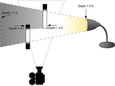
Shadow mapping has a very basic process. The idea is to render the scene from the light's point of view and record the distance between the vertex and the light source in a texture object. This texture is referred to as a depth map. Objects closer to the light source will have a small depth value (closer to 0.0) and objects furthest from the light source will have a larger depth value (closer to 1.0). There are two ways to record depth values. One is to use the projected z-coordinate (non-linear) and the other is to use linear depth. Both of these processes are described later. Once you generate this depth map, you then render your scene as you normally would from your camera's point of view. In your fragment shader, you perform lighting calculations as you normally would. As a final step, you determine if that fragment is in shadow by projecting its vertex from the light's point of view. If the distance between that vertex and the light source is greater than what is recorded in the depth map, then that fragment must be in shadow because something closer to the light source is occluding it. If the distance is less than what is recorded in the depth map, then that fragment is not in shadow and is probably casting its own shadow elsewhere in the scene. The stages are illustrated below.
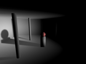
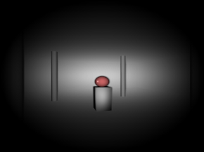

Left: As seen from the camera.
Middle: As seen from the light source.
Right: Depth as seen from the light source.
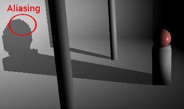
There's a couple caveats you need to be aware of before getting started with shadow mapping. Firstly, OpenGL ES 2.0 (WebGL) does not support the depth component texture format. In other words, you cannot render the depth values directly to texture. You must calculate this yourself and render the result to the colour buffer. This is not necessarily a bad thing. Traditionally the z-coordinate from a projected vertex was used for depth map comparisons in shadow mapping. The problem however is there is a loss of precision with this method, leading to something called "shadow acne".

Shadow acne is what happens when you perform comparisons with floating point values that are neck and neck with each other, which is a general problem in all forms of digital computing. What happens is the rounding error causes the shadow test to pass sometimes and fail other times, creating random spots of false shadows in your scene. One way to combat this issue is to apply a small offset to your polygons when rendering the depth map or a small offset to your shadow map depth calculations; however this can lead into another problem called "peter panning".

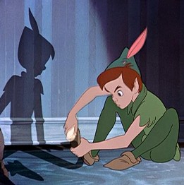
Image of Peter Pan and his shadow. From Walt Disney's "Peter Pan", 1953.
The term "Peter Panning" came from the fictional character Peter Pan, whose shadow could detach from Peter and either assist or jest with him at times. As shown from the screenshot above, shadow acne has been removed at the expense of shadows appearing disconnected from their sources due to using a large polygon offset.
One way to minimize both shadow acne and peter panning is to use linear depth. What this means is that instead of using the projected Z-coordinate, we instead calculate the distance between the vertex and the light source in view space. You still need to map the result between 0.0 and 1.0, so you would divide the value by the maximum distance a vertex can have from its light source (ie: the far clipping plane). You use this same divisor later in the shadow test to determine if a vertex is inside or outside of a shadow. The result is a depth value with much better and equal precision throughout the viewing frustum. It doesn't outright eliminate shadow acne, but it helps. When combined with filtering algorithms such as VSM or ESM (explained later), it's virtually a non-issue.
OpenGL ES 2.0 (WebGL) does not support the depth component texture format. We need to render the depth values into the RGBA fragment. This is performed in the depth.vs and depth.fs shaders. You want to pass in the light source projection and view matrices. If you're using perspective projection, you should use an aspect ratio of 1.0 and an FOV of 90 degrees. This will produce an even square with good viewing coverage. You can optionally use an orthographic projection for directional light sources like the sun. In the fragment shader, after you compute the distance and divide it by the far clipping plane, you need to store the floating point value into a 4x4 byte fragment. How do you do this? You use a carry-forward approach.
Example
Depth value = 0.784653
R = 0.784653 * 255 = 200.086515 = 200 (carry fraction over)
G = 0.086515 * 255 = 22.061325 = 22
B = 0.061325 * 255 = 15.637875 = 15
A = 0.637875 * 255 = 162.658125 = 162
The depth value 0.784653 is stored in an RGBA fragment with the values (200, 22, 15, 162).
When you need to retrieve the depth value, you simply reverse the operations. This is done as follows.
Depth = (R / 255) + (G / 255
Depth = (200 / 255) + (22 / 65025) + (15 / 16581375) + (162 / 4.2x10
Depth = 0.784313 + 0.000338 + 0 + 0
Depth = 0.784651
You can see from the original depth value and the unpacked depth value that there is an error of 0.000002, which is quite acceptable. You'll also note that the green and alpha channels have a huge divisor, which makes them practically irrelevant in restoring a floating point value. As such, you should expect to get at least 16 bit precision and up to at most 24 bit precision using this method.
You can find the code for packing a floating point value into an RGBA vector in the depth.fs shader. There is however one more process involved not outlined in the math above. GPUs have some sort of floating point precision or bias issue with the depth values you store in the pixel. While it's not documented anywhere, the consensus is to subtract the next component's value from the previous component to correct the issue. That is, R -= G / 255, G -= B / 255, and B -= A / 255. You will notice this being performed in the depth fragment shader.
Once you have your depth map, you need to render your scene from the camera and check if each fragment is in shadow or not by comparing its vertex depth value projected by the light source with the depth value stored in the depth map. In the fragment shader shadowmap.fs, you will see these comparisons at the bottom of the main function.
In order to know what pixel to sample in the depth map, you need to project your vertex using the light's projection and view matrix.
Where
if ( depth > rgba2float(texture2D(DepthMap, VL.xy)) )
{
	// Shadow pixel
	colour *= 0.5;
}
else
{
	// Pixel not in shadow, do nothing
}
The problem with standard shadow mapping is the high amount of aliasing along the edges of the shadow. You also cannot take advantage of hardware blurring and mipmapping to produce smoother looking shadows. To get around these issues, several filtering algorithms are discussed below.
Percentage closer filtering is one of the first filtering algorithms invented and it works by adding an additional process into the standard shadow mapping technique. It attempts to smooth shadows by analyzing the shadow contributions from neighbouring pixels.

The above example shows a 5x5 PCF filter. It doesn't use bilinear filtering so you can see how each neighbouring pixel is sampled. PCF can't operate on a blurred depth map. It requires an expensive 5x5 (or whatever kernel you wish to use) blurring operation for each fragment. While it's not recommended to use PCF, it does have the advantage of maintaining accuracy. It doesn't blur and thus "fudge" the depth map in order to get smoother shadows. With VSM and ESM, it's possible that blurring the depth map can produce false shadows, particularly along corners. It's a small tradeoff for an increase in speed.
Variance Shadow Maps and Exponential Shadow Maps were designed to eliminate the performance penalty involved in smoothing shadows using the PCF algorithm. In particular, they didn't want to perform blurring during the render stage. They wanted to take advantage of the separable blur algorithm, as well as anti-aliasing and mipmaps/anisotropic filtering. The example below demonstrates the results achieved by blurring the depth map and using one of the aforementioned filtering algorithms.
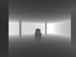

No blurring (standard shadow map look and feel).
3x3 blurring.
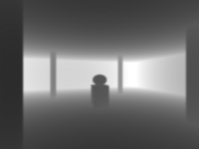
5x5 blurring.
The separable blurring technique (also known as the box-blur) gets its name from the way it performs blurring. In the traditional sense, blurring is performed using a convolution filter. That is, an N x M matrix that samples neighbouring pixels and finds an average. A faster way to perform this activity is to separate the blurring into two passes. The first pass will blur all pixels horizontally. The second pass will blur all pixels vertically. The result is the same as performing blur with a convolution filter at a significantly faster speed.


Left: Unfiltered image.
Middle: Pass 1, horizontal blurring applied.
Right: Pass 2, vertical blurring applied.
What's unique here is that the lower resolution depth map you use, the more effective the blurring. A 256x256 depth map for instance can produce a very nice penumbra, whereas a 1024x1024 depth map requires a large kernel to blur it sufficiently enough. You have to find the right balance between resolution and blurring. To much of either can hinder performance.
VSM and ESM are virtually identical in terms of output quality, but there is one significant difference between the two. VSM requires you store both the depth and the depth squared in the depth map. This requires a 64 bit texture, which is not available on older hardware or even within OpenGL ES 2.0 (WebGL). As such, you need to compute and store both values as 16 bit into the RG and BA channels of the pixel. While the precision loss isn't that bad, a proper implementation would require more memory than what ESM requires.
The VSM formula is presented below.
S = ChebychevInequality(M1, M2, depth)
Where
Chebychev's inequality function is what produces a gradient between 0.0 and 1.0 depending on whether or not the fragment is in shadow. The function is provided below.
float ChebychevInequality (vec2 moments, float t)
{
	// No shadow if depth of fragment is in front
	if ( t <= moments.x )
		return 1.0;

	// Calculate variance, which is actually the amount of
	// error due to precision loss from fp32 to RG/BA
	// (moment1 / moment2)
	float variance = moments.y - (moments.x * moments.x);
	variance = max(variance, 0.02);

	// Calculate the upper bound
	float d = t - moments.x;
	return variance / (variance + d * d);
}
The maximum variance you see in this function is configurable. I chose a value of 0.02 because that worked well within the 16 bit precision error. Adjusting this value can have both a positive and negative effect on your shadows. If you find you are getting a lot of shadow acne, you need to raise the maximum value; otherwise you can lower it until such point where shadow acne is not apparent. Once you have your shadow value calculated from Chebychev's inequality function, you multiply the value against the current fragment colour. Pixels not in shadow will return a value of 1.0 and pixels within shadow will return a value less than 1.0.
An alternative to VSM is ESM. ESM is probably one of the best ways to currently filter shadow maps. It's memory efficient in that it only requires you store the depth value in the depth map and you can still take advantage of blurring the depth map, generate mipmaps, anisotropic filtering, etc. The ESM formula is presented below.
S =
Where
Like VSM, the value returned from this function produces a gradient between 0.0 and 1.0. You take this value and multiply it against the current fragment colour. Pixels not in shadow will return a value of 1.0 and pixels within shadow will return a value less than 1.0.
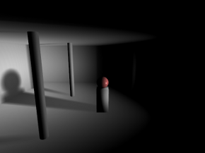
Point lights perform the exact same calculations as directional light sources, except you have to work with cubemaps. A point light may require up to six sides (left, front, right, back, top, and bottom) to receive shadows. This can add up to 6 times more calculations, which can have a significant impact on performance. If dealt with intelligently, you can deduce which sides of the cube are visible and perform only calculations on those faces. When possible, you should take advantage of multiple render targets to quickly produce depth cubemaps. OpenGL ES 2.0 (WebGL) unfortunately supports only one colour target, so that's not an option. Nevertheless, you should use point light shadows sparingly.
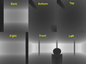
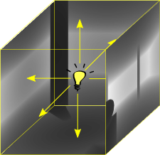
The above screenshot shows the depth map for each side of the cubemap. When performing depth map comparisons, you need to find out which side in the cube you will be working with. To do this, calculate the vector from the light source to the vertex. This will point to the location in the cubemap containing the depth sample to compare against. The final result is a room with shadows emitted on all sides.

This topic is not covered here, but it's one of the last remaining puzzles in shadow mapping. As you've seen by now what directional and point light shadow maps look like, the one problem not yet solved is what to do for large scale scenes. When you're outdoors and you can see the horizon, using a single depth map doesn't make much sense. You would never be able to accommodate all the detail in a single texture. This is where cascading comes into play. The idea is to split your viewing frustum into pieces, where each piece will have its own depth map to perform shadow comparisons. For a detailed review of these processes, check out Cascaded Shadow Maps on MSDN as well as GPU Gems 3 Chapter 10 Parallel-Split Shadow Maps.
| Unreal engine 4 - Interior level test WIP (0) | 2014.04.04 |
|---|---|
| Android에서 Adreno Profiler 사용하기 (0) | 2012.09.17 |
| 도움이 될만한 책을 반견한 것 같다! (0) | 2012.07.03 |
| Per-fragment lighting에서 alpha 값은 어디서 와야(?) 하는가!? (0) | 2012.06.18 |
| Normal을 구할 때, 방향(?)을 예측(?)하는 방법??? (0) | 2012.06.16 |
오늘 게게랩 TA편을 듣다가 그동안 내가 찾던 책이란 느낌을 받게 된 책이 있어서 급하게 검색 해 보았다.
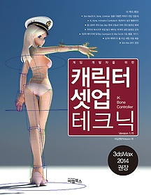 | 저자 이상원 출판사 비엘북스 3ds Max의 IK, Bone, Controller등을 이용한 캐릭터 셋업 전문서이 책은 3ds Max를 사용해서 게임용 캐릭터를 셋업하는 방법에 대해서 다루는 책이다. 특히 바이패드와 함께 Bone과 Controller를 제어하며 3D 캐릭터를 셋업하는 과정이 이 책의 핵심이며 이를 위해 오랜 실무를 경험해 온 저자의 고급 노하우들이 공개된다. 책 내용의 대부분이 게임 개발을 중심으로 설명이 되겠지만, 3ds Max 툴(IK, Bone, Controller 등)을 공부하기 위한 목적으로도 좋은 참고서가 될 것이다.IK / FK? Bone? Controller? Max Script? 개념부터 잡아준다!이 책은 캐릭터 셋업을 위해 반드시 알아두어야 할 기본 개념들, 즉 3D 좌표계의 이해부터 IK, B... |
위 책인데, 목록을 훑어보니 바로 내가 알고 싶었던 내용들이 들어있는 것이다!
그래서 바로 주문했는데 과연 어떨지는 읽어봐야 알겠지만, 득템 수준일 것 같다!!!
이 책을 읽고 3D 애니메이션에 대한 지식이 한단계 업그레이드 될 수 있으면 좋겠다!
(물론 노력없이 이룰 수 있는것은 없겠지ㅎㅎ)
P.S. 저자가 책을 위한 홈페이지도 운영하고 있고, 엔트리브에 근무하고 있다는 사실도 처음 알았다.
몇 달 전까지 바로 윗 층에 있었는데, 그저 신기할 따름. (엔트리브는 곧 이사를 간단다)
아래는 저자의 책에 대한 인터뷰 내용이다.

1. 간단한 소개 부탁한다.
현재 (주)엔트리브 에서 CTA(Chief Technical Artist) 및 그래픽 직군 총괄 역할을 하고 있습니다.
고등학교 시절 만화가 지망생이였고 집안의 반대로 미대 진학을 못하게 되면서 전산을 전공했는데, 현재 테크니컬 아티스트의 역할을 하게 된 배경에는 과거 이러한 과정이 큰 도움이 되었던 것 같습니다.
2. 이 책을 집필하게 된 이유와 이 책의 특징에 대해서 간단히 설명해달라.
셋업 혹은 리깅이라는 분야는 유난히 국내에서 관련 지식을 구하기가 쉽지 않은 분야 입니다.
하지만 그동안 게임 개발을 하면서 캐릭터 관절에 관한 문제들이 끊임 없이 발생했고 이런 필요에 의해 무작정 연구를 시작해서 실무에 적용을 했었습니다. 당시 저의 실험체가 되었던 애니메이터들에게 지금은 다소 미안한 마음이 드는군요. ^_^;
어깨와 엉덩이에 대해서 완벽한 해결책을 찾으려는 시도를 참 오랫동안 했습니다. 게임 개발때문에 바쁘다가도 아이디어가 떠오르면 어쩌면 무모하다고 할 정도로의 다양한 시도를 정말 많이 했습니다. 그러던 중 회사의 권유로 KGC라는 컨퍼런스에 캐릭터 리깅을 주제로 강의를 하게 되었고 이 강의를 계기로 리깅을 제법 잘 하는 사람으로 알려지기 시작하면서 집필 제의도 받게 되었습니다.
그동안 캐릭터 셋업이나 리깅 분야에 대해서는 일종의 취미 생활처럼 꾸준히 관심을 가지고 연구를 해왔습니다. 실제 업무는 과거부터 지금까지 게임 그래픽 전반을 모두 다루고 있는데 혹시 이 책으로 인해서 캐릭터 셋업 전문가로만 인식되면 어쩌나 하는 걱정도 해봅니다.^_^;
이 책은 쉽지 않은 주제를 다루고 있지만 최대한 실습 위주로 구성했기 때문에 독자들이 책을 읽으며 따라하다 보면 자연스럽게 알 수 있도록 구성했습니다. 그리고 필자의 목소리가 담긴 약 35여개의 동영상 강좌를 통해서 다소 어렵게 보일 수 있는 캐릭터 셋업 분야를 좀 더 친근하게 접근될 수 있도록 유도하려고 노력을 했습니다.
3. 어떤 사람(대상층)에게 추천해주고 싶은가?
이 책은 모델러에서 애니메이터가 되려고 준비하려는 분이나 현직 애니메이터 / 테크니컬 애니메이터/ 테크니컬 아티스트에게 많은 도움이 될 것입니다. 또한 필자의 노하우 뿐만 아니라 3D 애니메이션에 관련된 근본 원리와 개념을 모두 다루었기 때문에 3ds Max에서 애니메이션이나 리깅을 처음 공부하는 분들에게 강력하게 추천하고 싶습니다.
4. 이 책은 게임 개발자가 아닌 사람들에겐 어떤 도움이 될 수 있는가?
이 책은 게임 개발환경의 특성상 본(Bone) 중심의 셋업을 다루고 있습니다. 하지만 필름 컨텐츠 개발에서도 상당히 많은 부분이 본을 통해서 이루어지고 있으므로 3ds Max를 이용해서 움직이는 애니메이션 작업을 하는 모든 경우에 확실하게 도움이 될 것입니다.
5. 집필하면서 어려웠던 점이 있었다면?
책을 집필한다는 것이 이렇게 어려운 일인지 정말 몰랐습니다.
되돌이킬 수 없는 인쇄 매체로 출판되는 사실적 중압감은 정말 대단했습니다. 예전에 대략 짐작으로 알고 있던 수 많은 지식들에 대해서 3ds Max의 헬프 파일과 인터넷을 뒤져가며 모두 검증을 해야 했고 당장 필요가 없어서 중간 중간 몰랐던 부분들을 모두 채워 넣어야 했습니다. 물론 덕분에 많이 배우기도 했습니다.
콘솔 게임이나 PC 패키지 게임은 일단 출시되면 더 이상 수정할 수 없으므로 완벽한 QA와 검수 과정을 거치게 됩니다. 책 집필 작업 역시 이와 비슷한 느낌을 받았습니다. 하지만 출판사 담당자분이 컴퓨터 그래픽에 기반 지식이 많은 분이여서 좋은 결과물이 나오게 된 것 같습니다.
또 어려웠던 점이 있었다면 비키(여자캐릭터)와 랜디(남자캐릭터), 그리고 실시간 자동차 리깅 등 예제의 제작이였습니다.
처음에는 '알고 있는 것들을 정리하자' 라는 막연한 생각으로 시작했지만 예제 캐릭터의 모델링과 매핑, 그리고 완성된 리깅이 필요하게 되었고 이에 따른 예제를 만드는데 상당한 시간이 걸렸습니다.
결과적으로 초기 예상보다 5배 이상의 기간이 소요되었고 그동안 포기해야만 했던 개인적인 시간과 가족들과의 시간을 생각하면 정말 눈물이 나올 것 같습니다. 덕분에 좋은 내용이 담긴 책이 된 것 같아서 한편으로 뿌듯한 마음을 감출 수 없습니다.
6. 마지막으로 이 책을 재미있게 볼 수 있는 방법이 알고 싶다.
'셋업' 이라는 작업은 생각보다 재미있고 창의적입니다.
필자가 어렸을 때 갖고 놀던 '과학상자' 라는 장난감은 무언가를 조립하고 전선을 연결하고 서로 상호작용을 하면서 유기적으로 연계되는 장치를 만들어낸다는 재미가 있었습니다. 개인적으로는 과학상자를 선물로 받았을 때 기뻐하며 상상했던 재미를 '셋업'에서 느낄 수 있었습니다.
3ds Max 안에는 모터, 톱니바퀴, 전선, 철제 프레임, 나사와 볼트 등 모든 재료가 무한대로 준비되어 있습니다. 이 책을 보시는 분들도 제가 과학상자를 조립하며 느꼈던 재미있는 기억처럼 무한한 캐릭터 셋업. 리깅의 세계에서 함께 즐거움을 나눴으면 좋겠습니다. 감사합니다.
| Android에서 Adreno Profiler 사용하기 (0) | 2012.09.17 |
|---|---|
| Shadow Mapping (0) | 2012.07.18 |
| Per-fragment lighting에서 alpha 값은 어디서 와야(?) 하는가!? (0) | 2012.06.18 |
| Normal을 구할 때, 방향(?)을 예측(?)하는 방법??? (0) | 2012.06.16 |
| [퍼온글] Calculating Normals and Tangent Space (0) | 2012.06.14 |

|


